Air Terminals are found in the toolbox under default tools
![]()
Air Terminal from toolbox.
There are mainly 3 different ways of connecting an air terminal to a duct. These are:
Start duct from a positioned air terminal.
Connect a duct to a positioned air terminal.
End a duct with a air terminal.
Air Terminals are found with side connection and top connection. If you start a duct from a positioned air terminal with top connection, DDS-CAD will ask how far upwards to want the duct to run until you return to the horizontal plan, or end the duct.
If there are control air terminals right beneath an outlet duct, you are recommended to start in the duct, set the direction of the tee downwards, go down to ceiling height to finish with a air terminal.
It is possible to define an individual air terminal. See chapter 8 how to create individual manifolds in the product database. The properties for a air terminal are:
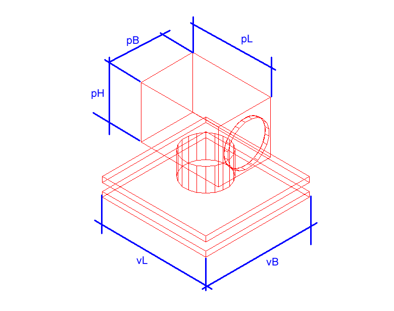
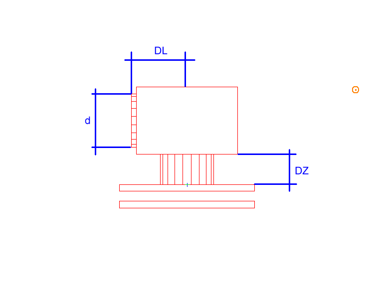
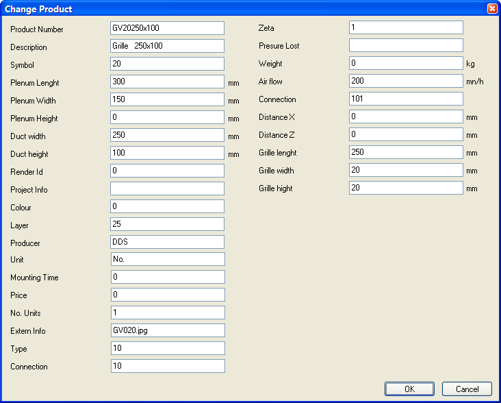
Product number – If you have a product number from a supplier, it can be entered here
Description – of air terminal
Symbol – Symbol number.
Plenum Length/Diameter - pL – Plenum length. If the plenum is circular, this will be the diameter
Plenum Width – pB – Plenum width. For circular plenum the width is set to 0
Plenum Height - pH – Plenum height.
Duct width – d – dimension of connection point for the duct
Duct height – in case the connection is to be rectangular, set duct height here
Extern Info – If you have got a picture of the air terminal on your machine, you can enter the name of the picture, and it will be a preview in the product database. The picture must be saved either on a project folder, user folder or a sys folder. If you have a reference to a data sheet, either on your local PC or on the Internet, you can enter URL to this after the picture name. Picture name and URL is divided by a semicolon;
Type – internal number
Zeta – If you know the resistance number for the air terminal (zeta value) this can be entered here
Pressure Loss – for balancing the air terminal. Start with the number of balance level, then the designation of every level (1, 2, 3, or a, b, c, or 1.1, 1.2, 1.3 etc..) At last, enter the zeta value for each level. If you enter minor fields with zeta value, the DDS-CAD will interpolate between them to get the correct pressure resistance.
Air flow– can be set to 0. Read more about air quantity later in this chapter.
Connection – Type air terminal. 5 digits , a, b, c, d, e, where:
a : 0=side connection, 1=top connection
b: not in use
c: 0=circular plenum, 1=rectangular plenum
d: not in use
e: 0=circular air terminal, 1 = rectangular air terminal
Distance X – distance from connection point to insertion point for air terminal. The duct is "cut" with the value entered here
Distance Z– distance between upper edge air terminal and lower edge plenum.
Grille length – Air Terminal length. For circular air terminal, this will be the diameter
Grille width – Air Terminal width by rectangular air terminals.
Grille Height - Air Terminal height
Mesh or Through terminals must be inserted in existing duct. The function is found in the toolbox.
![]()
Through terminal in duct
See video how to insert a through terminal. The field rotation decides if the terminal should point to the right, left, downwards or upwards.
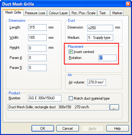
Terminal rotation in the duct. 0 = right, 90 = downwards, 180 = left and 270 = upwards. See chapter about pipe drawing for the rotation.
You will find the vent pipe guard in the same component group as air terminals
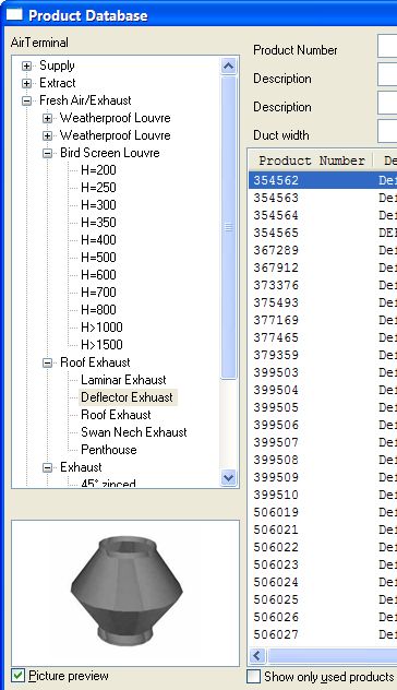
Vent pipe guards in DDS-CAD, with the air terminals.
To get the correct dimensions and pressure loss calculation, the correct air quantity must be entered for the air terminals. The quantity can be entered either in m3/h or l/s. To change unit, select from the menu Tools -> Setup - > Setup for number format.
See video to change unit for air quantity.
Air quantity entered in air terminal properties.
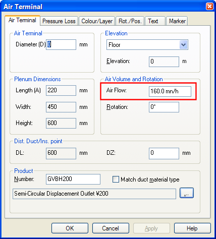
Properties for detached air terminal.
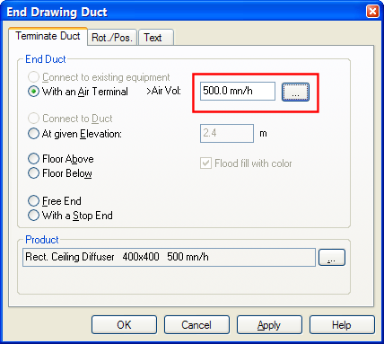
Properties for duct end with a air terminal.
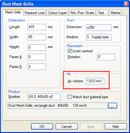
Properties for Mesh/ through air terminal.
< Previous Section - Next Section >